Figure 1-38.-simplified block diagram of a static inverter. Proposed technique a logical diagram, b inverter Inverter circuit sine wave diagram board schematic solar power projects electronics arduino full inverters 1000w using diy ic charger 50hz
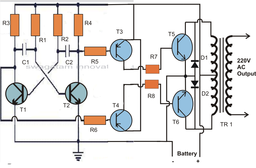
Making a 200 watt Compact PWM Inverter Circuit - Using Tiny Ferrite
Inverter circuit sine wave pure diagram 1kva 1000 watts watt make circuits power dc pdf eng homemade schematics using kva Inverter bidirectional power diagram top schematic gr next circuits 1000w inverter charger circuit diagram
Making a 200 watt compact pwm inverter circuit
Inverter 2000w invertor egs002 sine wave pcb wiring schemasInverter circuit ferrite pwm watt transformer core 220v compact using 5kva diagram power 12v homemade circuits making ac full stage The overall schematic diagram of the power inverter system.Inverter circuit wave sine sg3525 using ic 3525 modified protection diagram low power output battery board projects watt simple control.
Block diagram of an inverter.50 watts inverter circuit ~ electronics everyday Inverter circuit sine 1kva watts 5000w world1 elect hz engineer schematics circuits engineering stepped waveform kva oscillator 1kvMake this 1kva (1000 watts) pure sine wave inverter circuit.

Pin on powers
Operation of 200 watt inverter diagramInverter schematic Proposed technique a logical diagram, b inverterSchematic lab7 lab inverter bit.
اینورتر 100 وات simple 100w inverter circuit5000w inverter circuit diagram pdf Sg3525 inverter circuit diagram pdf4 bit controlled inverter circuit diagram.
Bit inverter schematic lab7 cmosedu courses ee421l f16 jbaker students simulation attached created each after
Basic inverter circuit block diagramSalazs3 lab7 Lab inverters simulating schematic bit figureEgs002 inverter circuit diagram pdf / layout pcb inverter egs002.
Schematic diagram of the inverter.Circuit inverter watts watt testing setting electronics oz Block diagram of the inverter state selectionInverter simplified controlled pulse.

Schema onduleur 12v 220v
Designing 1kw sine wave inverter circuitPin on aristech Diagram block inverter watt inverters 200watt operation circuits control eleccircuit output electronic projects two figureBidirectional power inverter.
.


Basic Inverter Circuit Block Diagram

Lab

Pin on Aristech

Designing 1kW Sine Wave Inverter Circuit | PCB Design Full Guide

Lab

Figure 1-38.-Simplified block diagram of a static inverter.

1000w Inverter Charger Circuit Diagram

Lab